 Wiring Colors & Symbols
Colors

Example of a wiring diagram.
Wiring diagrams are typically colored with lines representing the following:
- Red = Control Circuit(s)
- Blue = Neutral Wire
- Green = Ground Wire
- Black/White (varies on background) = Power Source
Symbols
Download Wiring Symbol Chart ( PDF, 768.7 KB)
| Symbol | Description |
|---|---|
 |
Auto-Off Selector Switch |
 |
Auto-Off-Continuous Selector Switch |
 |
Lead-Off-Lag Selector Switch |
 |
Lead-Off-Lag-Continuous Selector Switch |
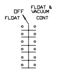 |
Float-Off-Float and Vacuum Continuous Selector Switch |
 |
Disconnect |
 |
Starter, Single-Phase with a Set of Two Overloads |
 |
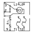
Starter, Three-Phase with a Set of Three Overloads |
 |
Starter Coil with Three Overloads |
| Transformer to Reduce Supply Voltage to 115 volts for Control Circuit Operation | |
 |
Relay with Two Normal Open and Two Normal Closed Contacts |
 |
Electric Alternator Alternates Between Two Pumps Equalizing Operation Time |
 |
Single Pole, Single Throw Float Operated Switch to Turn Pumps On and Off |
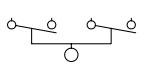 |
Double Pole, Single Throw Float Operated Switch to Turn Pumps On and Off |
 |
Pump Motor |
 |
Fuses |
 |
Circuit Breaker |
 |
Alarm Bell for Use with High and Low Water Conditions |
 |
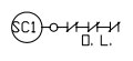
Low Water Cut-Off Switch, Normally Closed for Use with Electrical Panel with One Transformer |
 |
Low Water Cut-Off Switch, Normally Open for Use with Electrical Panel with Two Transformers |
 |
Pilot Light to Indicate Power On or System Operation |
 |
Terminal Block |
 |
Float Switch and Solenoid for Adding Make-up Water |
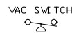 |
Vacuum Switch |
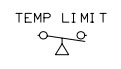 |
Temperature Limit Switch |
 |
End Switch |
 |
Mechanical Alternator, Mechanically Alternates Between Two Pumps to Equalize Operation Time |
 |
Push Button for Momentary Make of Electrical Circuit. Used as Test Button or Push to Silence in Alarm Circuit. |